Typical installation locations
Recommended mounting locations for earthing brushes
Our earthing brushes are designed to allow them to be installed in a wide variety of locations and positions on the machine.
Caution: The earthing brushes may only be mounted and run on surfaces made of carbon steel or low-alloy steel. Never on aluminum, titanium, austenitic stainless steel or other materials with poor wear properties.
Never run a brush on a surface subject to high stress, especially if vibration stresses are present. Example: quill shafts, hollow coupling spacers, areas with stress concentration.
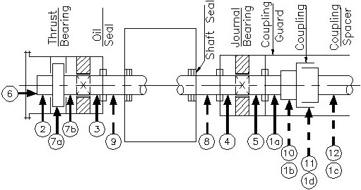
The installation options shown in the above illustration are arranged in such a way that the effectiveness and resistance of a brush decreases (as the number increases) with consecutive numbering. More precisely, this refers to the factors that affect effectiveness, suitability for use, environmental conditions and protection against damage.
Mounting locations 1-12
(1a) Between clutch hub and bearing housing, mounted on a clutch guard.
Only possible with integrated clutch hub!
(1b) Rides on the clutch hub. Only with conductive clutch (e.g. type "Flex-Disk" or "Diaphragm"), plus integrated hub.
(1c) Rides on the spacer for couplings.
(1a-1c) Installations in these areas may require oil spray for cooling and/or lubrication.
(1d) Installed on the outer clutch surface (check surface speed).
(2; 3; 4; 5) Installed in the bearing housing, between the bearing and the outer seal. Installed on the bearing housing. Or mounted in the outboard cover of the bearing end.
(7a) Mounted on the outer diameter of the integral thrust collar. Check wind force, oil flow and speed (less than 150 m/sec or 500 ft/sec).
(7b) Installation between thrust bearing and plain bearing.
Interim conclusion: All of the above-mentioned areas can be considered good locations. If such a location is not possible, the following can be considered, taking precautionary measures into account:
(8; 9) Installation options between the gas seal (vapor seal) and bearing housing.
Common disadvantages are: Poor surface finish and rust, exposed environment, abrasive particles in the air, hot steam or gas blowing against the brush from one side, and oil leakage on the other side, leading to gumming and coking. In addition, a lack of reliable oil lubrication.
Conclusion: The other end of the machine has more moderate operating conditions and is therefore preferred for installation.
(10) Installed on a shrunken coupling hub.
Possible problems are: Excessive and heavy currents can heat up the area, causing the hub to loosen.
Spot welding of the hub to the shaft when high currents are present.
Unreliable electrical contact between hub and shaft, especially after friction and/or corrosion and/or high currents.
(11; 12) Installed on the coupling sleeve or on the spacer shaft.
Possible problems: The problems are the same as those mentioned above. In addition, the shaft currents must flow through the coupling teeth. This can lead to deterioration of the teeth with subsequent blocking of the coupling, resulting in vibrations and possible failure of the coupling and/or thrust bearing.
Important: The problems described in (11) and (12) do not occur with conductive couplings, e.g. with diaphragm types ("Flex-Disk" or "Diaphragm").
Additional comments and precautions for installation solutions in the range (8) to (12):
While arrangements (8) to (12) have clear disadvantages compared to arrangements (1) to (7), it would still be worse not to install and use brushes at all. The reason for this is that the currents would flow through the teeth even without brushes, so that the teeth would also shrink as a result, which would then cause the same damage, only faster and with greater consequences. In addition, with the installation of a brush, the current flow can be monitored so that the device can be switched off for demagnetization if the currents become too strong. Without a brush, there would be no warnings, so any damage found would already be too great.
Sequence of the preferred earthing brushes to be installed (decreasing from the top):
- Type L earthing brush: Most desirable if space permits.
- Type S earthing brush: For confined spaces.
- Type A earthing brush: For retrofitting on site or if type L or S cannot be installed.
- Type LW earthing brush: For large turbine generators or propeller shafts.