Prevention
Why are wave currents important?
Solving the shaft current problem is crucial for all turbomachinery applications, as problems with the shaft current can lead to considerable additional costs. On this page, you can find out more about the formation and effects of shaft currents and how our products provide effective protection against stray shaft currents. You will also find typical damage patterns with brief descriptions.
The solution to the shaft current problem is of crucial importance for all turbomachinery applications!
Shaft currents are caused by the build-up of electrical charges on the machine shaft through 3 mechanisms: static discharge resulting from the flow of particles in liquids, motor and generator faults and the movement of magnetized components. The charge build-up creates a potential difference (voltage) between components, which is discharged by sparks. Sparking occurs when the voltage between the components exceeds the breakdown voltage of the liquid separating them, usually oil. The voltage at which sparking begins depends on a variety of factors, such as the distance between the components, the type of oil and the oil impurities, and ranges from 0.5 volts for rolling bearings to over 10 volts for large liquid bearings. Typically, sparks occur at the points with the smallest distance between stationary and rotating components.
Spark discharges generate intense heat (over 2500 °C), which causes pitting at both ends of the spark. Depending on the energy level of the sparks, this can lead to a slow and gradual erosion of the bearing material, sometimes taking years before the damage becomes noticeable in rising bearing temperatures. Or the sparking can be so severe that the machine cannot operate for more than a few hours before it has to be shut down. Problems with the shaft current can lead to considerable operating costs.
What can be done to protect machines from wave currents?
In some cases, shaft current is inherent to the process, so compressors, turbines and pumps are all subject to significant static discharge loads. Fortunately, static discharges are usually low energy events that can be dissipated to ground with careful design. On the other hand, magnetized components and motor/generator faults can cause high energy discharges and the only effective long-term solution is to correct the underlying fault. Regardless of the source of the shaft current energy, Sohre brushes can protect sensitive machine components and keep your machine running.
Sohre Turbomachinery® shaft grounding brushes use a proprietary silver and gold fiber compound that makes reliable electrical contact with the shaft, ensuring low electrical contact resistance and low contact pressure. As a result, there is little mechanical wear on the brush or shaft surface. Compared to solid brushes made of graphite, carbon or other materials, Sohre brushes have a significantly lower contact resistance. Shaft grounding brushes from Sohre Turbomachinery® eliminate deterioration of the shaft surface and the resulting loss of contact during prolonged operation in normal through-current operation. Solid brushes from other manufacturers, on the other hand, which are commonly used on electrical machines, have a much higher resistance after wear and therefore start to spark, leading to a deterioration of the shaft surface. If the resistance of the installed brushes is then higher than the resistance inside the machine, the currents no longer flow through the brush, but through the machine, which can lead to damage.
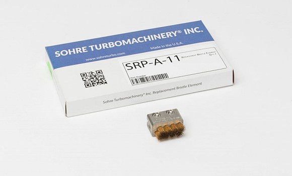
Brushes from Sohre
Sohre's brushes are characterized by excellent electrical conductivity, so that the brushes ensure very low electrical noise, even at high surface speeds and in aggressive environments. This, a low wear rate and easy replaceability enable long-term monitoring and dissipation of electrical discharges during system operation.
Sohre brushes are preferred in the industry over other grounding solutions such as copper braids, carbon blocks and other conventional tools due to their superior performance and low maintenance requirements.
There are now more than 10,000 brushes in use worldwide - in chemical plants, refineries, paper mills, drilling platforms, oil fields, ships, power generation plants, cryogenic processes, wind turbines and many other facilities. Several original equipment manufacturers (OEMs) use our brushes as standard equipment for their customers.
Get in touch with us
Find out more about possible solutions to your current problems.
Surface damage to bearings made of Babbitt metal
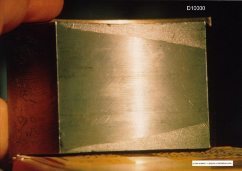
D10000
Damage to a bearing due to short circuits in a unipolar generator.
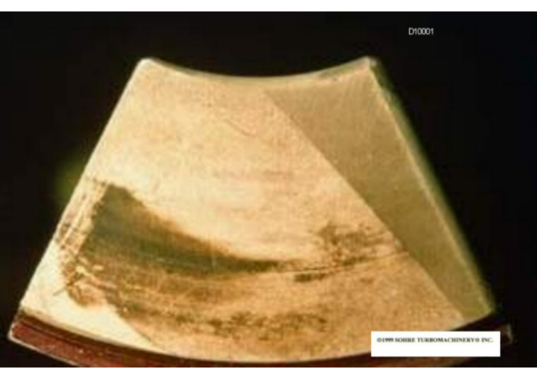
D10001
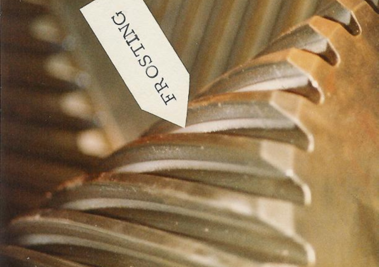
Thrust bearing, which is severely damaged by wave currents (icy surface). The wedge-shaped area at the leading edge (right) is the only remaining original surface. At the white triangle at the trailing edge (outer diameter), the metal coating from Babbitt has completely disappeared and the spark erosion has penetrated into the steel back. The metal loss at this point is 0.085″. The dark brown area represents oil residue. Furthermore, the bearing was about to fail.
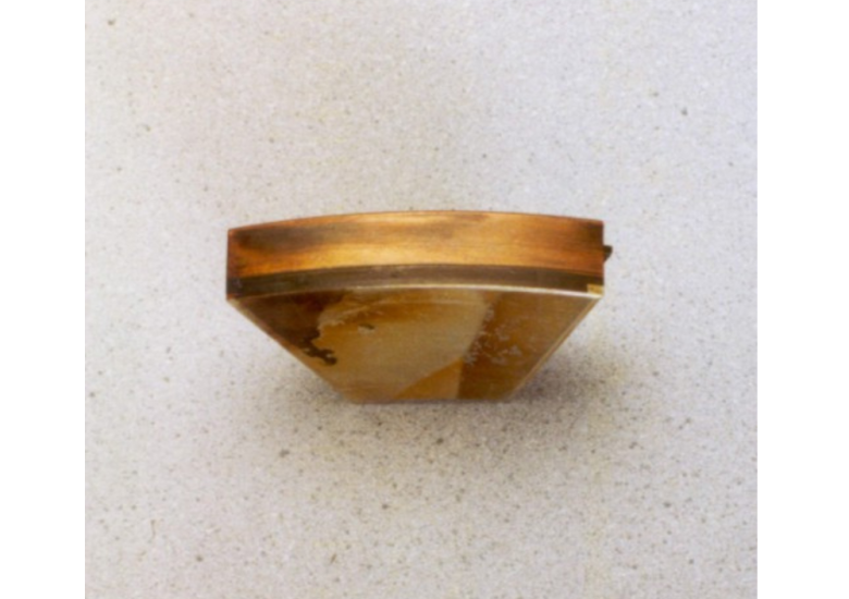
D10002
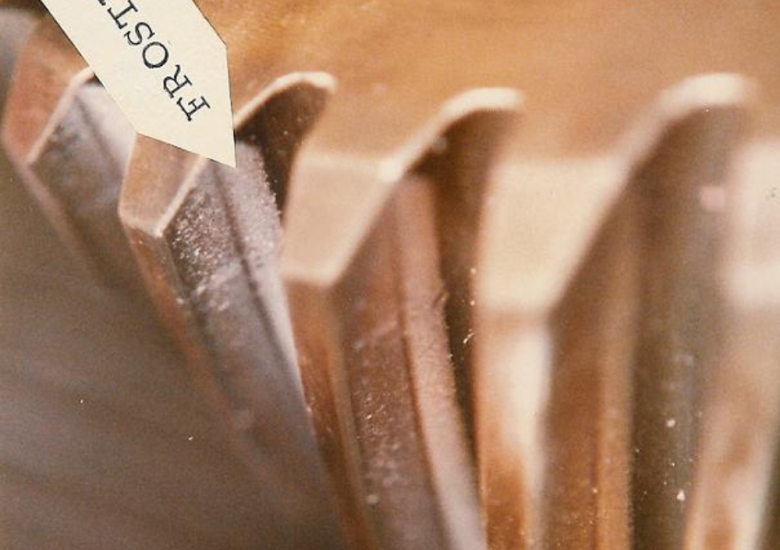
Surface of a thrust bearing showing damage caused by spark erosion. Here you can clearly see how the babbitt surface has been progressively eroded from right to left. The original and remaining babbitt surface is at the bottom right.
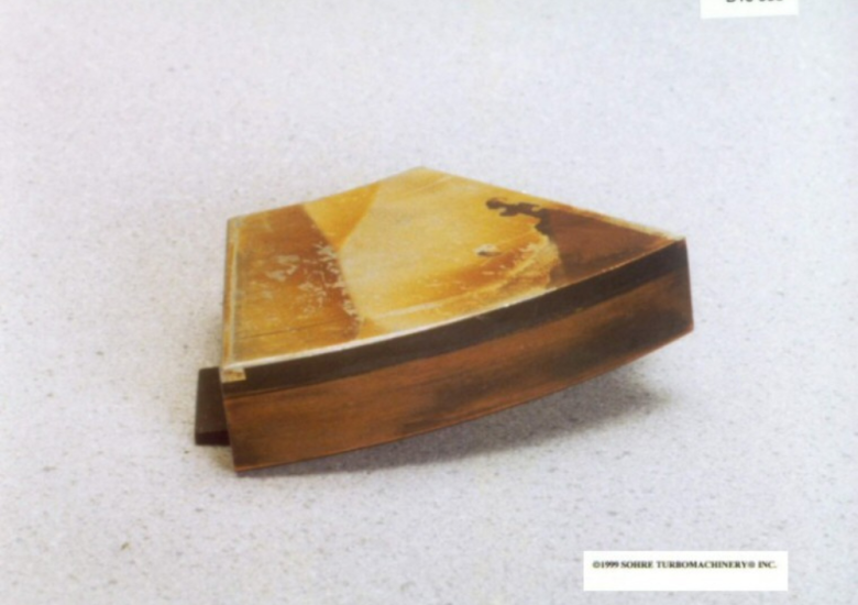
D10003
Surface of a thrust bearing damaged by spark erosion (same item as D10002, just a different perspective). Here you can see again how the babbitt surface was gradually eroded from left to right. The babbitt coating has been completely removed in the bottom right corner.
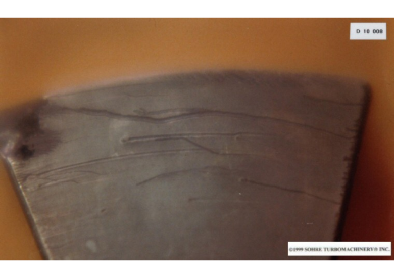
D10008
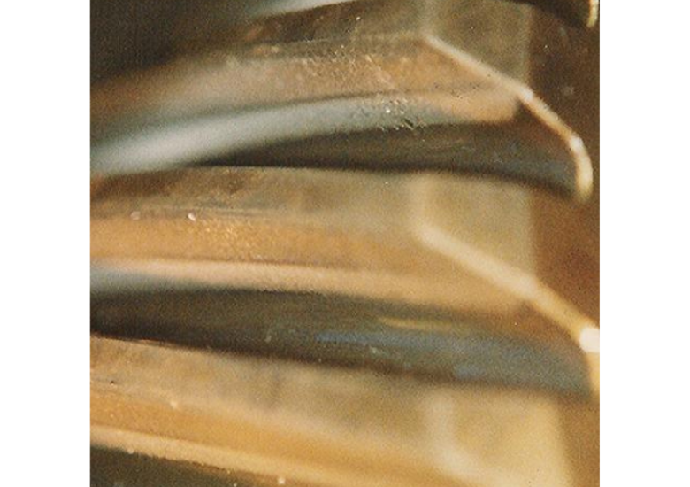
Typical spark paths that can be found on a thrust bearing.
D10009
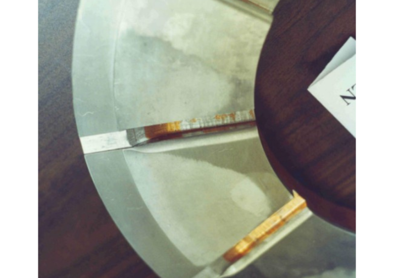
Axial bearing, with the surface covered with a moderate matt finish due to spark erosion. This device is equipped with OEM carbon brushes. This is why we recommend our brush technology.
D10010
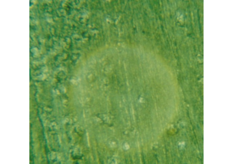
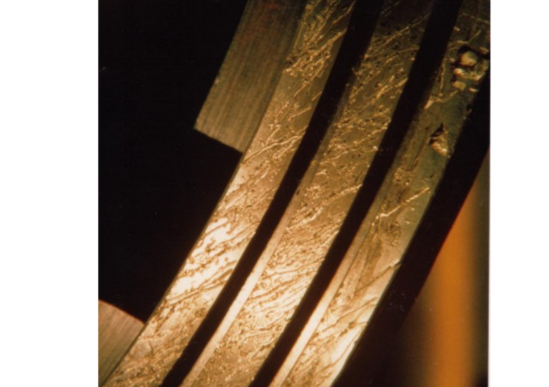
Visible interface between the "frosted" area and the original surface at 30x magnification under the microscope (same support surface as shown in D10009).
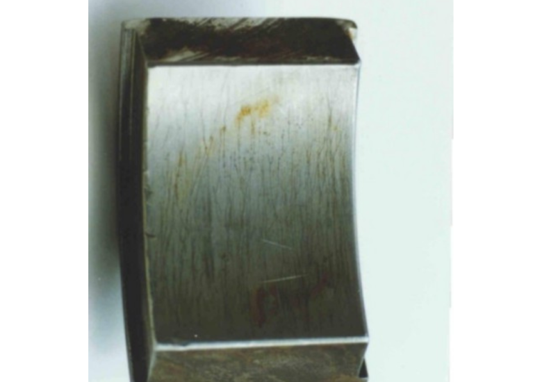
D10049
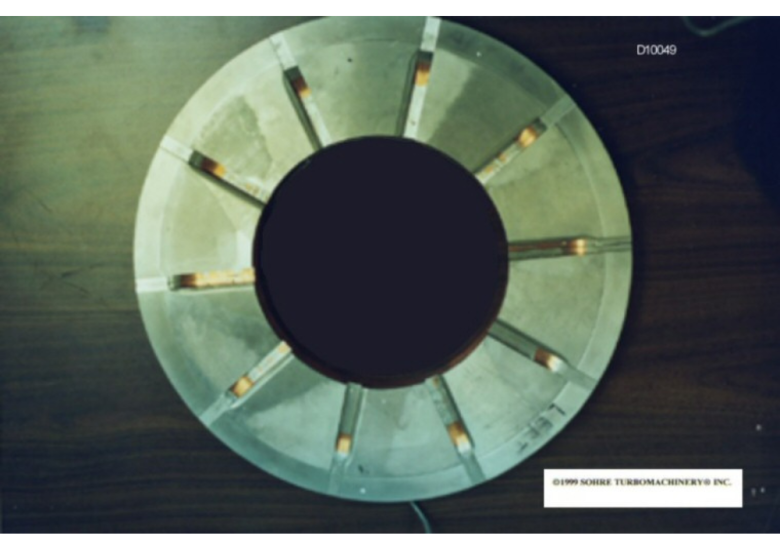
Thrust bearing surface of the fixed plate damaged by spark erosion. General view of the bearing used in D10009.
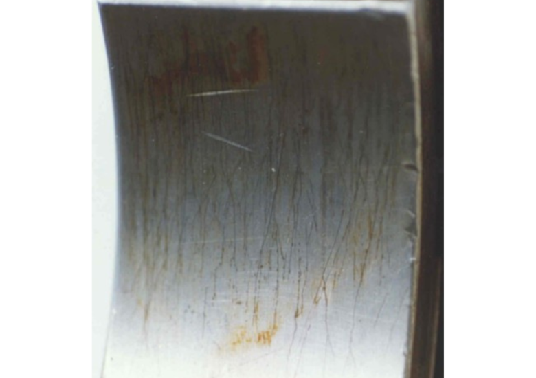
D10051
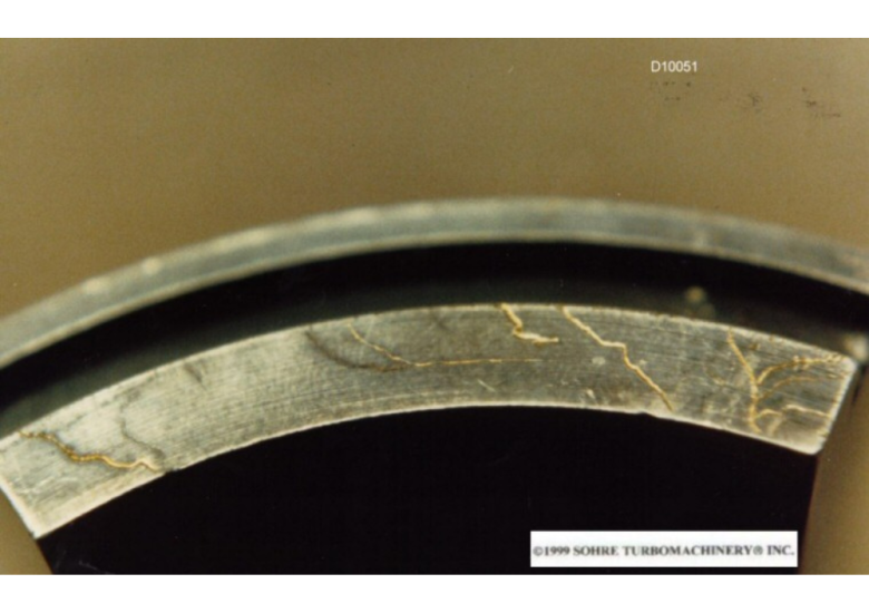
Spark marks on the tilting pad slide bearing.
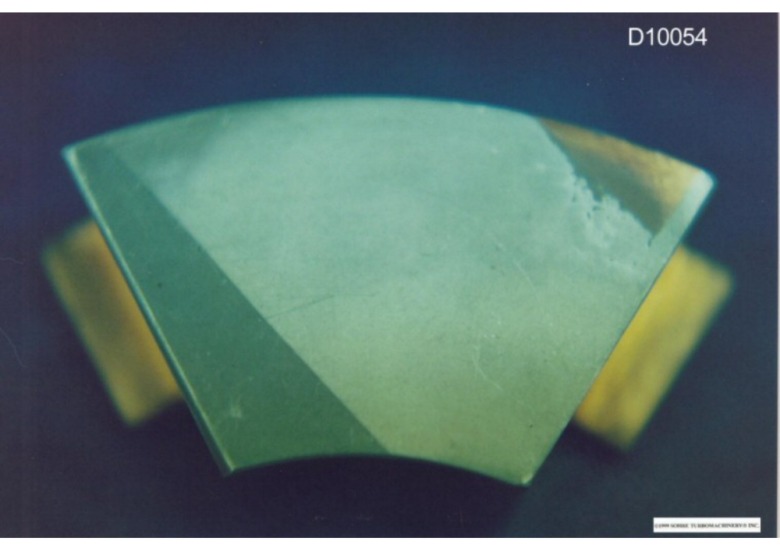
D10054
Axial bearing pads, damage due to shaft currents.
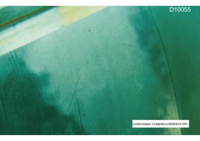
D10055
Axial bearing pads, damage due to shaft currents (enlargement of D10054).
D10040
Tilting plate for plain bearings with spark gaps.
D10045
Tilting plate for plain bearings with spark gaps.
Surface damage to the shaft bearing
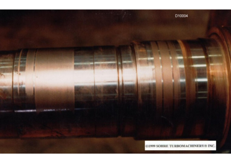
D10004
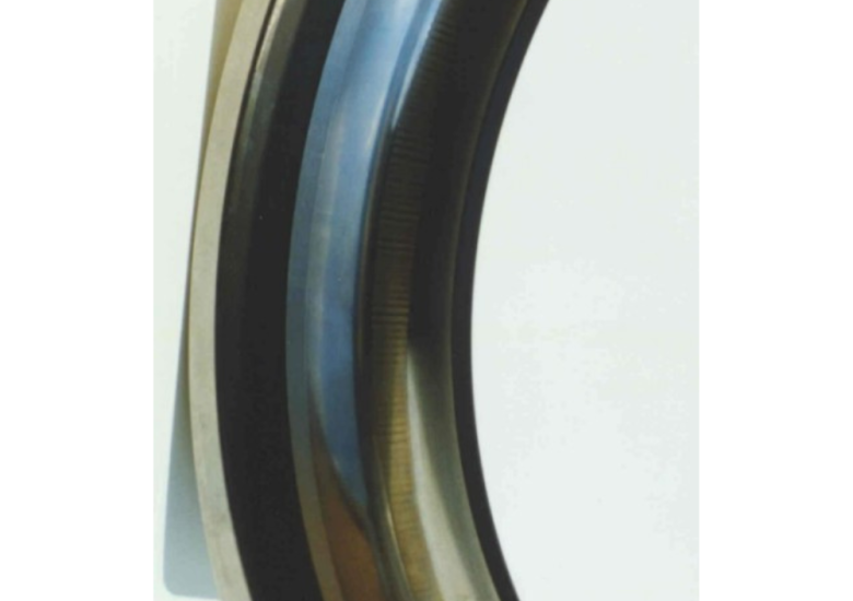
Typical "frosting" in the bearing and sealing area. This case is unusual in that the "frosting" area only extended to 50% of the circumference.
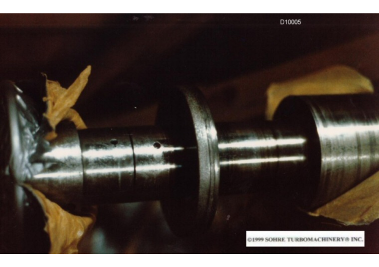
D10005
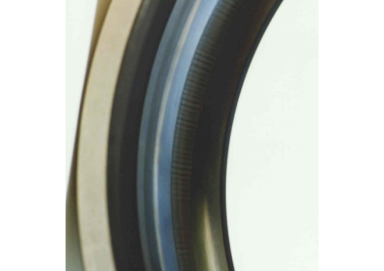
Outer surface of the rotor severely damaged by wave currents.
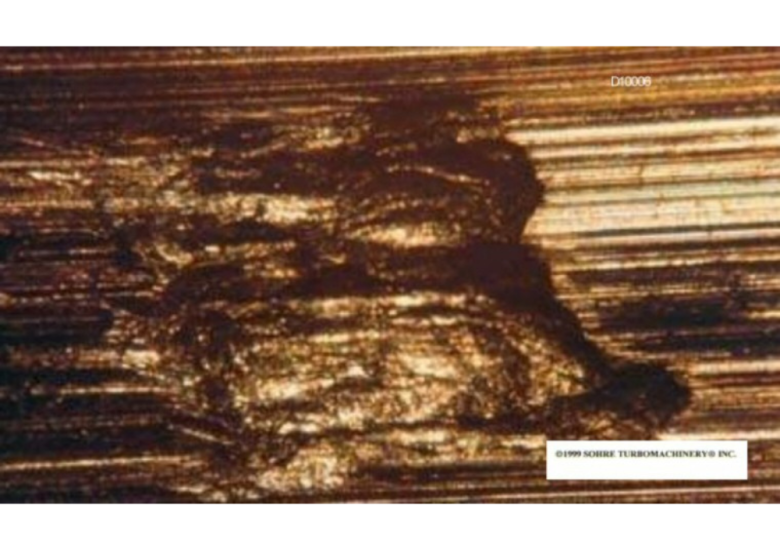
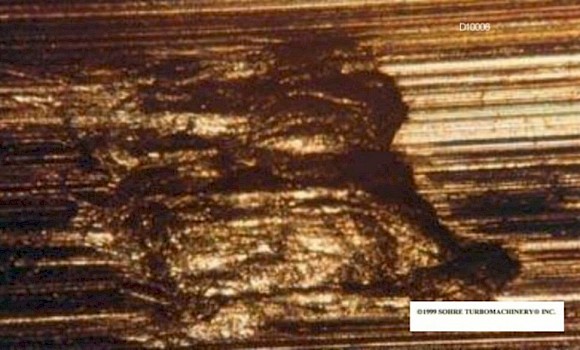
D10006
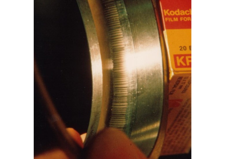
Spark groove on the wave surface (enlarged).
Examples of a strongly magnetized turbine rotor
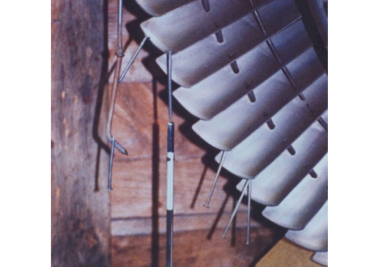
D10011
Turbine rotor that was magnetized so strongly that nails and a small mirror could be attached to the blades. The magnetism was caused by unintentional friction between the rotor and stationary parts.
Get in touch with us
Find out more about shaft currents and how you can avoid them in practice.
Damage to the rolling bearing
D10012
Ball bearing. The inner barrel was damaged by electrical wave currents. The surface was matted by spark erosion.
D10038
Spark erosion on the rolling bearing.
D10039
Spark erosion on the rolling bearing.
Damage to the gearbox
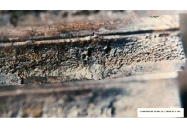
D10052
Damaged clutch tooth due to spark erosion.
D10060
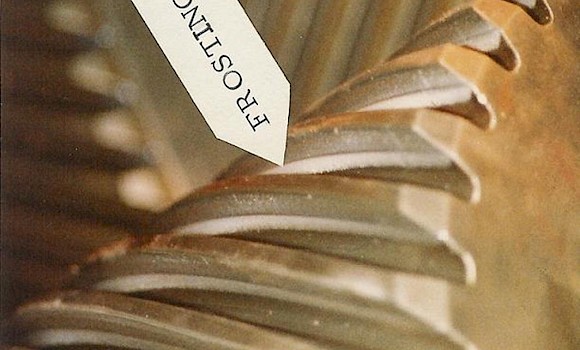
Gearbox damage (frosting) due to spark erosion.
D10061
Gearbox damage (frosting) due to spark erosion.
D10062
Gearbox damage (frosting) due to spark erosion.
Other machine damage
D10014
Strong spark paths in the bushing seal of a synthetic gas compressor (28,000 kW, 11,000 rpm).
D10015
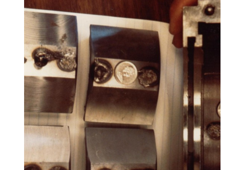
Bearing shoes (steel) on an ammonia system / air compressor turbine (7,500 kW, 8,000 rpm). Due to a failure, the thrust bearing was welded to the bearing cage.
D10021
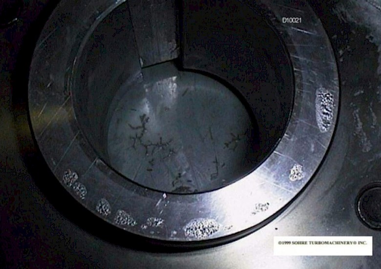
Shaft current damage to a gearwheel.
D10025
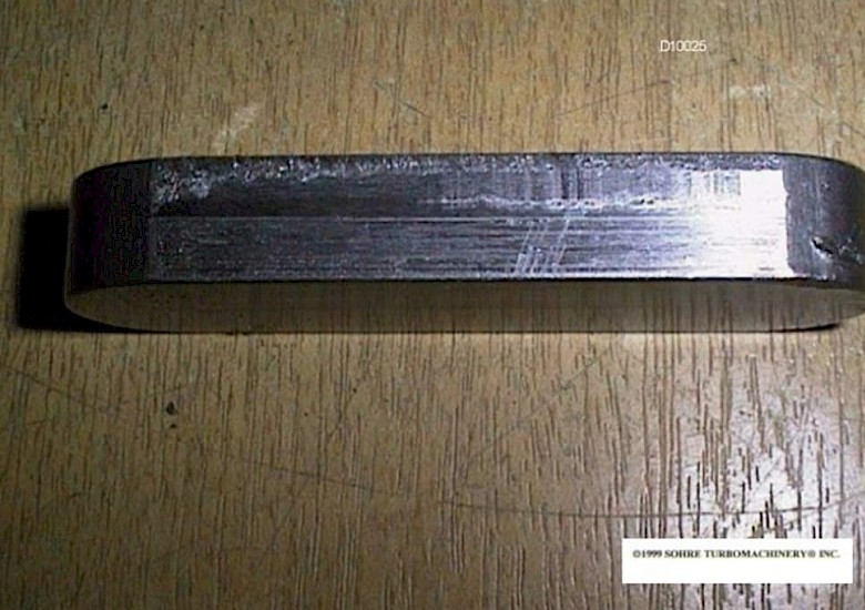
Spark pitting on a gear key.